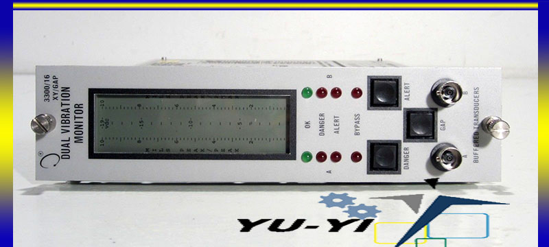
3300 Bently Nevada Manual

• Operation and Maintenance Manual Bently Nevada™ Asset Condition Monitoring 1900/27 Vibration Monitor Part Number 190127-01 Rev. F (09/07) • 1900/27 Vibration Monitor Operation and Maintenance Manual Copyright 1994. Game Blood Omen 2. Bently Nevada LLC. All rights reserved.

Counter bore, sideview or rearview restrictions limit the use of standard Bently Nevada* 3300 and 3300 XL 5 and 8 mm Transducer Systems. It is also ideal for. Shop for the GE Bently Nevada 3300 XL Proximity Probe and other Vibration Monitoring at Instrumart. Download and Read Bently Nevada 3300 Manual Bently Nevada 3300 Manual Many people are trying to be smarter every day. How's about you? There are many ways to evoke. Specifications and Ordering Information 3300 XL 8 mm Proximity. (refer to Specifications and Ordering Information. Other than a Bently Nevada AISI 4140.
The information contained in this document is subject to change without notice. The following are trademarks of the legal entities cited: Sealtite® is a registered trademark of Anamet Inc. • Contact Information The following ways of contacting Bently Nevada are provided for those times when you cannot contact your local representative: Mailing Address 1631 Bently Parkway South Minden, Nevada USA 89423 Telephone 1.775.782.3611 1.800.227.5514 1.775.215.2873 Internet www.ge-energy.com/bently. • 1900/27 Vibration Monitor Operation and Maintenance Manual Additional Information Notice: This manual does not contain all the information required to operate and maintain the product.
Refer to the following manuals for other required information. 200150, 200155, and 200157 Accelerometers Information and Installation Guide (Part Number 164985-01) 89129 and 190520 Accelerometer User Guide (Part Number 89134-01) Product Disposal Statement.
• Contents 1. 1900/27 Vibration Monitor Description..
1 Features....1 Monitor Connections, Indicators, & Controls..4 2. 6 Receiving Inspection...6 Jumper Settings....6 2.2.1 Setting Relays for Latching or Non-Latching Behavior..7 2.2.2 Setting Relays for Normally Energized or Normally De-energized Behavior.7 2.2.3 Setting 4 to 20 mA Interface Behavior During 1900/27 Monitor Bypass. • 1900/27 Vibration Monitor Operation and Maintenance Manual Setpoint Adjustment...26 Resetting the Monitor...28 Buffered Transducer Output...28 Initiating a Monitor Self Test...28 4. Maintenance & Troubleshooting..29 General Maintenance...29 Monitor Adjustments...30 4.2.1 LCD Zero Adjustment...30 4.2.2 Adjustment of the Monitor's 4 to 20 mA Current Loop Interface. Torrent The Wire Season 1 720p Movies. 32 Troubleshooting....35 5. • Section 1 - 1900/27 Vibration Monitor Description 1. 1900/27 Vibration Monitor Description The 1900/27 Vibration Monitor provides continuous vibration monitoring for machinery where most of the shaft vibration is transmitted through the bearing to the case. Vibration amplitude is a primary indicator of the overall mechanical condition of rotating machinery.
• 1900/27 Vibration Monitor Operation and Maintenance Manual Relay BYPASS - A relay BYPASS switch lets you disable both relays while you adjust the relay setpoints or maintain the machinery. This feature prevents false alarms or undesired machinery shutdowns.
When the monitor is bypassed, the red BYPASS LED is on. • Section 1 - 1900/27 Vibration Monitor Description Programmable options provide flexibility and a wide range of standard features. Internal Jumper Options: Normally Energized/De-energized Relays - The Alert and Danger relays can be be either normally energized or normally de-energized.
The normal condition of a relay corresponds to its non-alarm condition. • 1900/27 Vibration Monitor Operation and Maintenance Manual segments turn on at the beginning of the self test to verify that they are operating properly.
The power supplies are checked continually. 1.2 Monitor Connections, Indicators, & Controls The connections, LEDs and LCD, and control switches are shown in the next three figures.